Date published: 2022-06-18
Improving the periodic error and guiding ability of a Losmandy GM8 mount
Why bothering about improving Losmandy’s GM8 mount
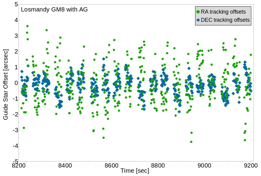
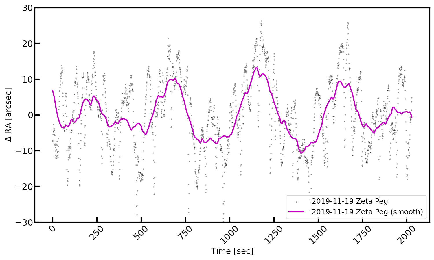
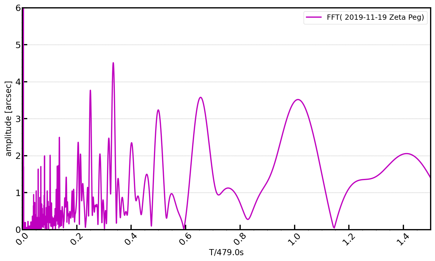
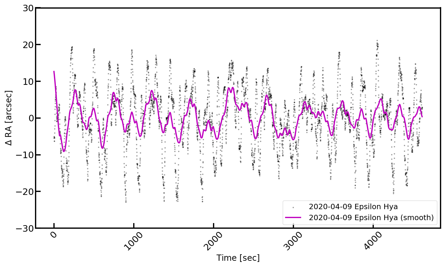
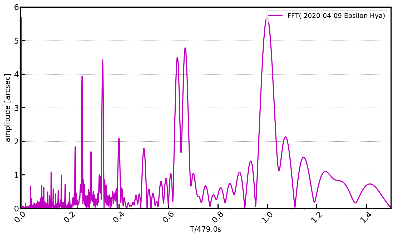
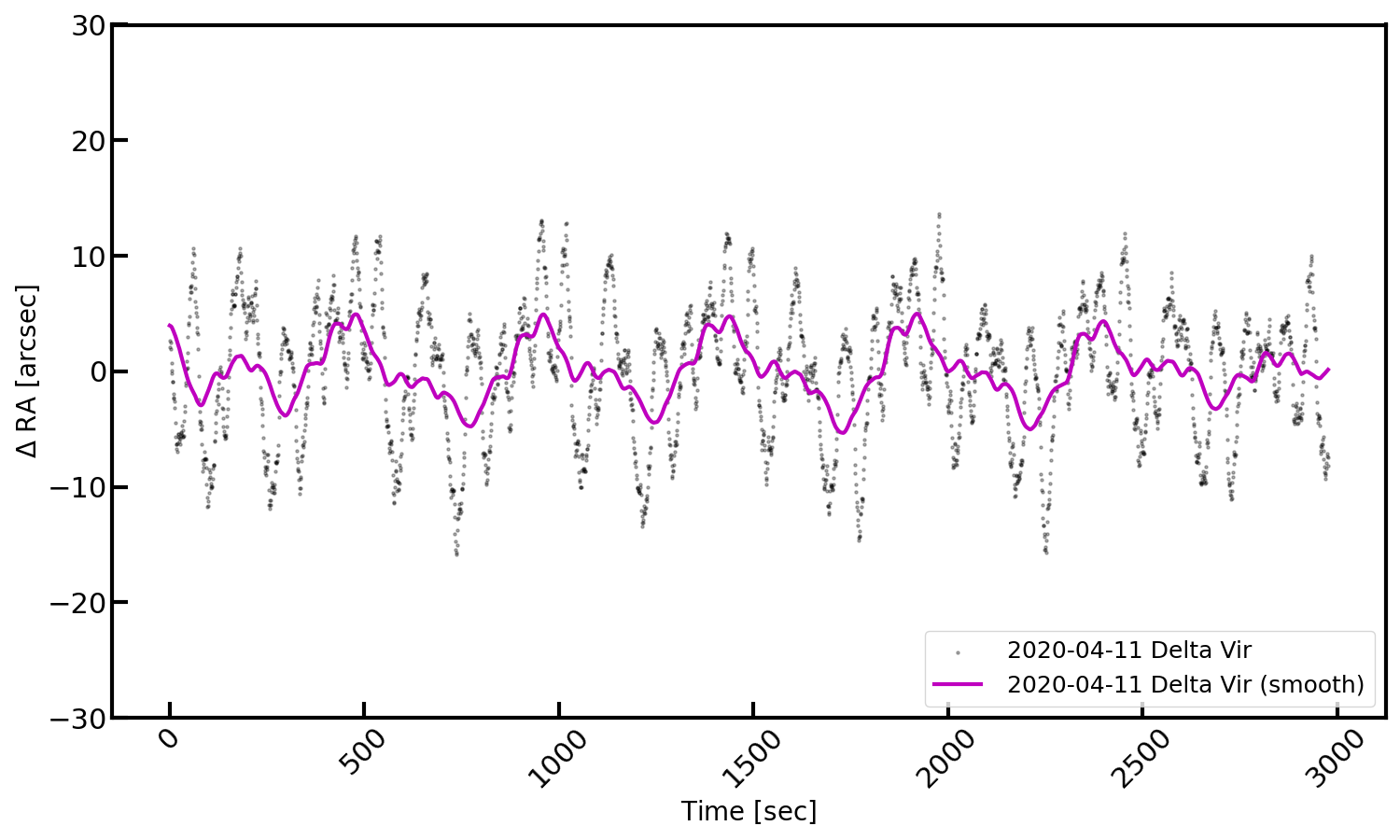
As mentioned in an earlier post, I have purchased a used GM8 mount for less than 800 EUR (including motors, digital drive system, tripod and polar scope), hoping that this mount will allow smooth auto-guiding. Indeed, the GM8 does not show severe problems such as large jumps in declination (like many other cheap and light mounts such as EQ5). Thus, guiding principally works (see Figure 1). However, the Losmandy GM8 mount I got does show high-frequency peaks in RA on top of the periodic error (see Figure 2 and 3 and previous post), which negatively affect image quality, i.e. it blows up the star images when doing long exposures. For that reason, I decided to make some improvements (that’s what this post is about), hoping that this will finally allow multi-minute exposure times and perfectly round stars close(r) to the seeing-limit.
Step 1: Upgrade to high-precision ABEC-7 worm bearings
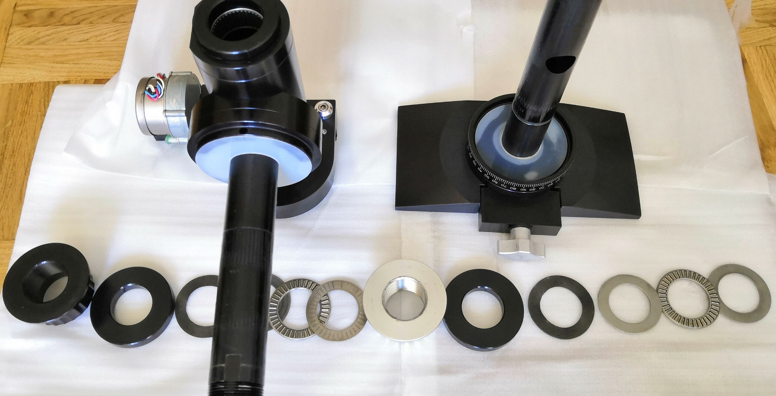
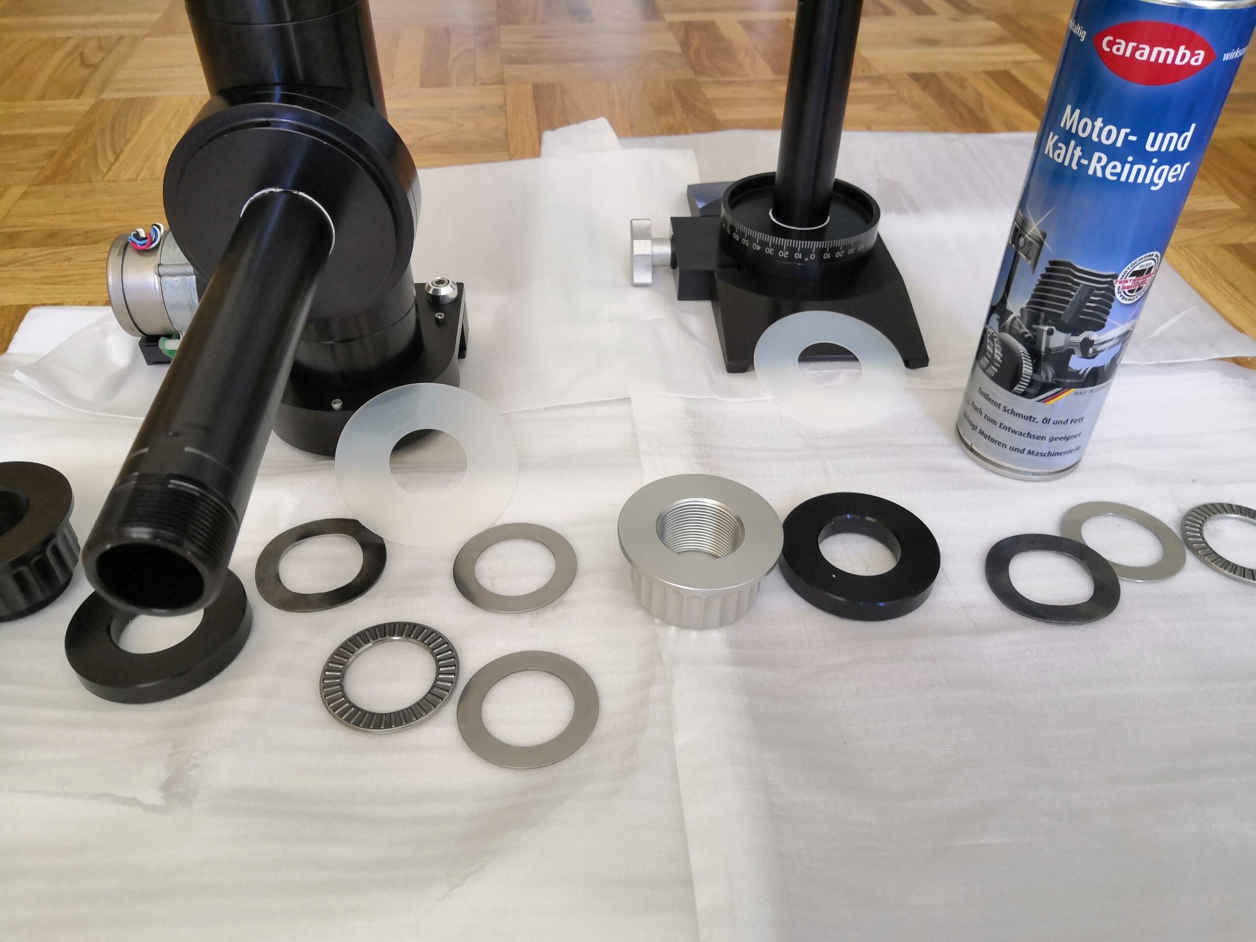
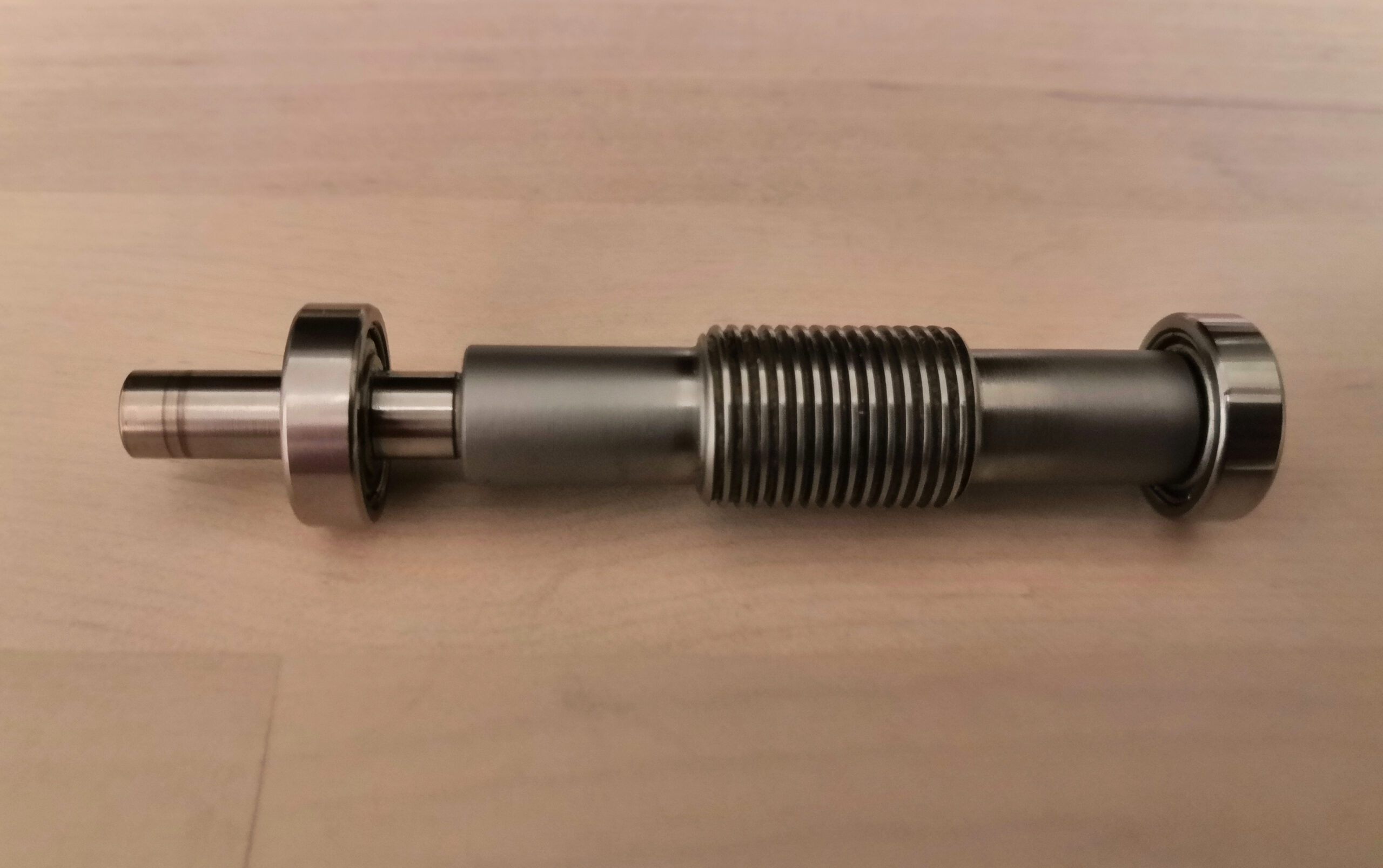
The very first step of improvement consists of disassembling, cleaning and re-greasing. This is necessary as with time lubricant and/or grease accumulates on the nylon discs that are located between the pressure plates and gear surfaces (see Figure 4). The slippy nylon discs then prevent the clutches to work properly, i.e. only when clutches are very strongly tightened the axes can be fixed. After cleaning (see Figure 5), the original worm bearings were exchanged with high precision ABEC-7 bearings that I purchased from the Boca Bearing Company under part number SR4-ZZC #7 PS2 (see Figure 6). Finally, the mount was re-greased and re-assembled.
The periodic error of the mount after this upgrade is shown in Figures 7 and 8. As a result, the amplitudes of the highest frequencies have decreased by a factor of ~2; compare left parts in Figures 3 and 8 where periods are <0.2T, with T being the worm period of 479s. However, the tracking curve is still dominated by high-frequency signals with peak-to-peak amplitudes of roughly +/-20arcsec.
Step 2: Sanding the bearing blocks and preload the worm bearings with disc springs
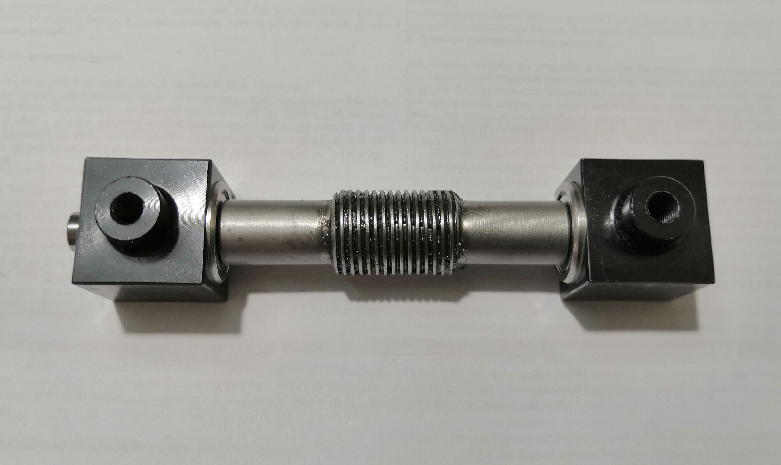
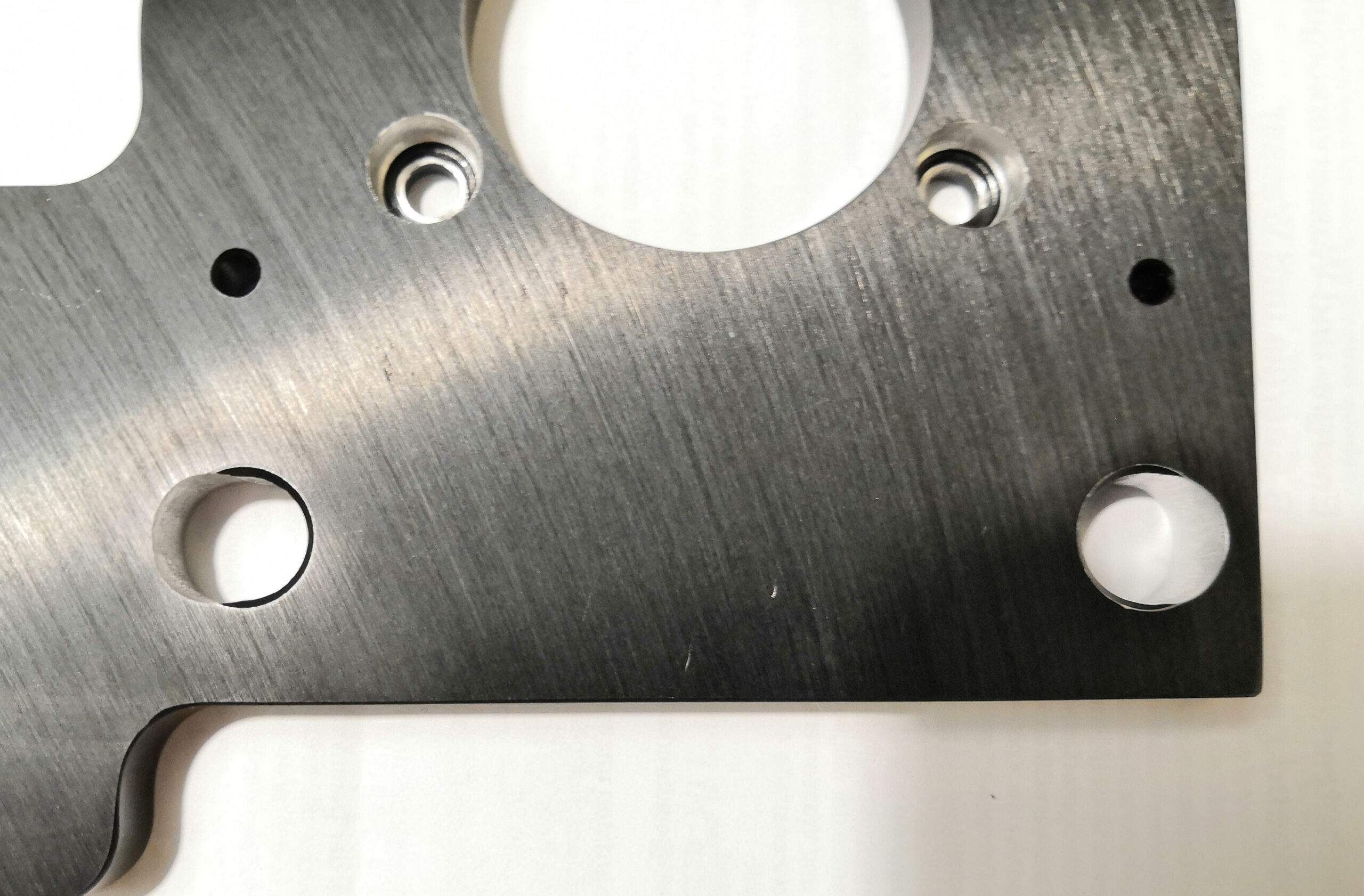
I recognized that the worm bearings sit very firmly in their mounting cubes. Thus, I decided to sand and polish (using a very fine sanding sponge) the inner parts of the RA and DEC worm bearing mounting cubes and preload the bearings using disc springs (see Figure 9), which I purchased from Key Bellevilles Inc under part number 625 634 EL. The specifications of the disc springs are: outer diameter: 0.62in, inner diameter: 0.32in and thickness: 0.0098in. Due to the extra space needed by the disc springs, the distance between the mounting cubes of the modified worm blocks has increased (see e.g. Figure 10 for RA). Thus, the holes to mount the worm block on its mounting plate were extended using a round file (see e.g. Figure 11 for RA).
After re-assembling the mount, the periodic error measurement (Figures 12 and 13) shows that all the efforts payed off. The high-frequency peak-to-peak amplitudes could be reduced by a factor of ~2 to a level of roughly +/-10arcsec.


Step 3: Lapping the worm and wheel
The final step is to lap the worm and the worm wheel together to smooth off any imperfections. To do so, I used Macolaepp K2000 diluted 1:50 with Liqui Moly LM47 grease. After applying the mix to both, the worm wheel and the worm gear, I used a cordless screwdriver to spin around the worm and worm wheel several times in both directions until the worm could be turned easily by hand at all positions of the worm wheel without shifting and no recognizable backlash. Once both axes were lapped, I carefully removed the lapping paste, re-greased and re-assembled the mount.
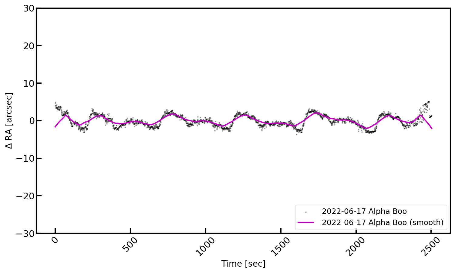
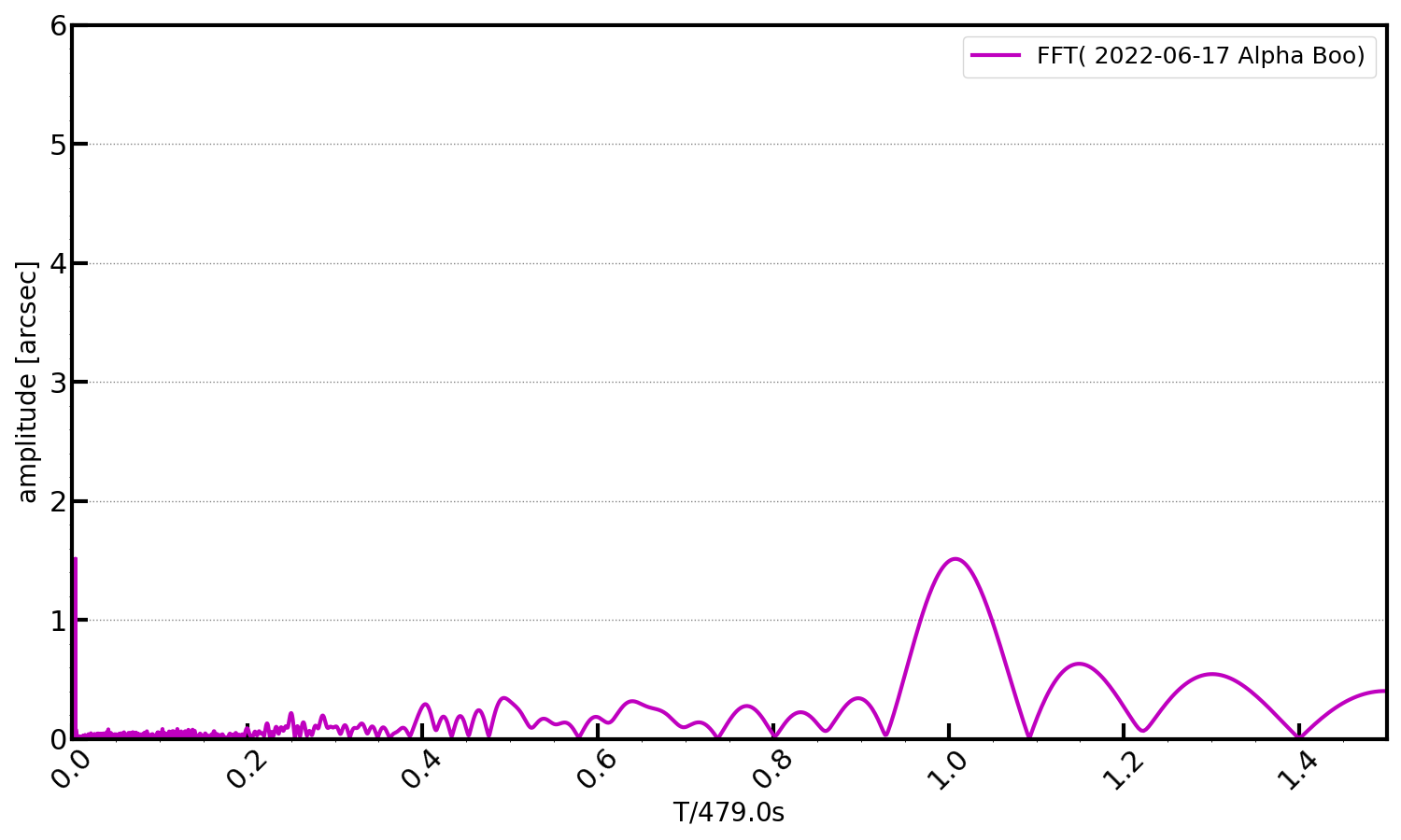
Finally, the tracking curve does not show any high-frequency disturbances and is characterized by the periodic error only, with an amplitude better than +/-2arcec (see Figures 14 and 15). That’s quite impressive!